
Efficient Rijndael Encryption Implementation
with Composite Field Arithmetic
Atri Rudra
1
, Pradeep K. Dubey
1
, Charanjit S. Jutla
2
, Vijay Kumar
,1
,
Josyula R. Rao
2
, and Pankaj Rohatgi
2
1
IBM India Research Lab, Block I, Indian Institue of Technology,
Hauz Khas, New Delhi, 110016, India
{ratri,pkdubey,vijayk}@in.ibm.com
2
IBM Thomas J. Watson Research Center,
P.O.Box 704, Yorktown Heights, NY 10598, U.S.A.
{csjutla,jrrao,rohatgi}@watson.ibm.com
Abstract. We explore the use of subfield arithmetic for efficient imple-
mentations of Galois Field arithmetic especially in the context of the
Rijndael block cipher. Our technique involves mapping field elements to
a composite field representation. We describe how to select a represen-
tation which minimizes the computation cost of the relevant arithmetic,
taking into account the cost of the mapping as well. Our method results
in a very compact and fast gate circuit for Rijndael encryption.
In conjunction with bit-slicing techniques applied to newly proposed par-
allelizable modes of operation, our circuit leads to a high-performance
software implementation for Rijndael encryption which offers significant
speedup compared to previously reported implementations.
1 Introduction
In October 2000, the US National Institute of Standards and Technology (NIST)
announced that it had selected the Rijndael Block Cipher [3] as the new Ad-
vanced Encryption Standard (AES). In addition to being the new standard,
Rijndael is a cipher that offers a good “combination of security, performance,
efficiency, implementability and flexibility” [20]. It has already attained consid-
erable popularity and acceptance. Rijndael is a block cipher with a block size of
16 bytes, each of which represents an element in the Galois Field GF (2
8
). All
operations in Rijndael are defined in terms of arithmetic in this field.
Apart from Rijndael, there are several other instances of the use of Galois
Field arithmetic in cryptography and coding theory [10]. The efficiency and
performance of such applications is dependent upon the representation of field
elements and the implementation of field arithmetic. It is common practice to
obtain efficiency by careful selection of the field representation [9,10,11]. In par-
ticular, it is well-known that the computational cost of certain Galois Field
As of April 2001, the author can be reached at Amazon.com, 605 5
th
Ave South,
Seattle, WA 98104, U.S.A.
C¸ .K. Ko¸c, D. Naccache, and C. Paar (Eds.): CHES 2001, LNCS 2162, pp. 171–184, 2001.
c
Springer-Verlag Berlin Heidelberg 2001
172 A. Rudra et al.
operations is lower when field elements are mapped to an isomorphic composite
field, in which these operations are implemented using lower-cost subfield arith-
metic operations as primitives [11]. Depending upon the computation involved
and the choice of representation, there are costs associated with the mapping and
conversion, and a trade-off has to be made between such costs and the savings
obtained. The design task is to carefully evaluate these trade-offs to minimize
the computational cost.
In addition to an efficient hardware implementation, a good circuit design is
also useful in obtaining fast software implementations. Using the technique of
bit-slicing [2] a circuit with a small number of gates can be simulated using a
wide-word processor. Multiple instances of the underlying computation are thus
performed in parallel to exploit the parallelism implicit in a wide-word computer.
This technique has been used in [2] to obtain a fast DES implementation.
In this paper, we study the use of composite field techniques for Galois Field
arithmetic in the context of the Rijndael cipher. We show that substantial gains
in performance can be obtained through such an approach. We obtain a compact
gate circuit for Rijndael and use its design to illustrate the trade-offs associated
with design choices such as field polynomials and representations. We use our
circuit design to obtain a simple and fast software implementation of Rijndael
for wide-word architectures. The performances of both hardware as well as soft-
ware implementations show large gains in comparison with previously reported
performance figures.
The rest of this paper is organized as follows. In Section 2, we detail the map-
ping of Galois Field operations to composite field arithmetic. Section 3 outlines
the data-slicing technique for realizing a highly parallel software implementation
from a circuit design. In Section 4, we describe the mapping of Rijndael opera-
tions to a particular class of composite fields. The selection of field polynomials
and representations and the associated optimizations are discussed in Sections
5 and 6 respectively. Finally, in Section 7 we present our results and a compari-
son with previously reported performance figures for Rijndael. Drawings of our
Rijndael encryption circuit are included in the Appendix.
2 GF Arithmetic and Composite Fields
Composite fields are frequently used in implementations of Galois Field arith-
metic [9,10,11]. In cases where arithmetic operations rely on table lookups, sub-
field arithmetic is used to reduce lookup-related costs. This technique has been
used to obtain relatively efficient implementations for specific operations such as
multiplication, inversion and exponentiation. Much of this work has been aimed
at implementation of channel codes. The object has usually been to obtain better
software implementations by using smaller tables through subfield arithmetic.
Applications to hardware design (such as [10]) have been relatively infrequent.
Our techniques are directed at both hardware and software implementations.
We take advantage of the efficiency obtained by the use of subfield arithmetic,
not merely in the matter of smaller tables but the overall low-level (gate count)
An Efficient Rijndael Encryption Implementation 173
complexity of various arithmetic operations. The computation and comparison
of such gains and cost is dependent upon several parameters – the overhead of
mapping between the original and the composite field representations, the na-
ture of the underlying computation and its composition in terms of the relative
frequency of various arithmetic operations, and in case of software implemen-
tations, the constraints imposed by the target architecture and its instruction
set. Based on these parameters we select the appropriate field and representa-
tion to optimize a hardware circuit design. As we shall see, there can be several
objectives for this optimization, such as critical path lengths and gate counts,
depending upon the overall design goals. The circuit design obtained can then
be used to obtain parallelism in a software implementation by means of slicing
techniques.
As described in [11], the two pairs {GF (2
n
),Q(y)} and {GF ((2
n
)
m
),P(x)}
constitute a composite field if GF (2
n
) is constructed from GF (2) by Q(y) and
GF ((2
n
)
m
) is constructed from GF (2
n
)byP (x), where Q(y) and P (x) are
polynomials of degree n and m respectively. The fields GF ((2
n
)
m
) and GF (2
k
),
k = nm, are isomorphic to each other. Since the complexity of various arith-
metic operations differs from one fieldto another, we can take advantage of the
isomorphism to map a computation from one to the other in search of efficiency.
For a given underlying field GF (2
k
), our gains depend on the choice of n and m
as well as of the polynomials Q(y) and P (x).
While we restrict our description to composite fields of the type GF ((2
n
)
m
),
it is easy to see that the underlying techniques are fully general and can be used
for any composite field.
3 Slicing Techniques
Bit-slicing is a popular technique [2] that makes use of the inbuilt parallel-
processing capability of a wide-word processor. Bit-slicing regards a W -bit pro-
cessor as a SIMD parallel computer capable of performing W parallel 1-bit op-
erations simultaneously. In this mode, an operand word contains W bits from
W different instances of the computation. Initially, W different inputs are taken
and arranged so that the first word of the re-arranged input contains the first
bit from each of the W inputs, the second word contains the second bit from
each input, and so on. The resulting bit-sliced computation can be regarded as
simulating W instances of the hardware circuit for the original computation. In-
deed, a bit-sliced computation is designed by first designing a hardware circuit
and then simulating it using W -bit registers on the rearranged input described
above.
A bit-sliced implementation corresponding to an N -gate circuit requires N
instructions to carry out W instances of the underlying computation, or N/W
instructions per instance. This can be particularly efficient for computations
which are not efficiently supported by the target architecture. Consider for in-
stance GF (2
8
) multiplication on AltiVec [4]. The straightforward implementa-
tion uses three table-lookups and one addition modulo 255. 16-parallel lookups
174 A. Rudra et al.
in a 256-entry table can be performed on AltiVec in 20 instructions. Thus, a set
of 128 multiplications would require 488 instructions. In comparison, our 137-
gate multiplication circuit translates into a bit-sliced implementation that can
perform 128 multiplications in 137 instructions!
The above computation ignores the cost of ordering the input in bit-sliced
fashion and doing the reverse for the output. To evaluate the trade-off correctly,
this cost has to be taken into account as well. In general, this cost will depend
on the target instruction set.
However, it is possible to think of scenarios in which a particular operation
may be efficiently supported in an architecture. For example, if the AltiVec ar-
chitecture were to provide an instruction for 16 parallel GF (2
8
) multiplications
which use the underlying field polynomial of interest to us (a hypothetical but
nonetheless technically feasible scenario since the critical path of the multipli-
cation circuit is only six gates deep), then a direct computation would require
only eight instructions, compared to the 137 required by the bit-sliced version.
Now consider GF (2
16
) multiplications on this hypothetical version of the
AltiVec architecture. It is easy to see that the most efficient computation is
neither a direct one, nor a bit-sliced version, but a byte-sliced computation, in
which each GF (2
16
) multiplication is mapped to a small number of GF (2
8
)
operations, which are efficiently supported by the architecture in question. In
general, the right “slice” to use would depend on the target architecture.
3.1 Encrypting without Chaining
Our Rijndael implementation processes 128 blocks of data in parallel. Tradi-
tionally, such a scheme would be regarded as more useful for decryption than
for encryption, since encryption is usually performed in inherently sequential
modes such as Cipher Block Chaining or CBC [17,18,19]. The well-known CBC
[17,18,19] is used as a defense against replay attacks [12]. In the CBC mode of
encryption, parallel blocks would not be available for encryption except where
data from many streams is encrypted in parallel.
However, a new parallelizable variant of CBC [7] removes this limitation and
makes it possible to use CBC encryption without the usual sequentiality. This
makes it possible to utilize the high throughput rates of our implementation in
conjunction with the popular CBC mode.
4 Rijndael in a Composite Field
Rijndael involves arithmetic on GF(2
8
) elements. In a straightforward implemen-
tation, inverse, multiplication and substitution are likely to be the operations
that determine the overall complexity of the implementation. The most common
approach is to use table lookups for these operations. By mapping the operations
into a composite field, we are able to obtain both a small circuit in case of a
hardware implementation as well as smaller instruction counts and table sizes
in case of software implementations.
An Efficient Rijndael Encryption Implementation 175
For our Rijndael implementation, we work in the composite field GF ((2
4
)
2
).
We selected the field polynomial Q(y)=y
4
+ y + 1 for GF(2
4
). For P (x), we
consider all primitive polynomials of the form P (x)=x
2
+ x + λ where λ is an
element of GF (2
4
). There are four such polynomials, for each of which there are
seven different transformation matrices to consider, one corresponding to each
possible choice of basis. The criterion used by us to compare various choices is
the gate count of the resulting Rijndael circuit implementation.
Rijndael operations translate to the composite field representation as follows.
H denotes the mapping from GF (2
8
)toGF ((2
4
)
2
), and T the corresponding
transformation matrix — that is, H(x)=Tx. S isa4× 4 matrix (the state)on
which all operations are performed.
– ByteSub transformation : This has essentially two sub-steps:
1. P
ij
=(S
ij
)
−1
. In the composite field, H(P
ij
)=(H(S
ij
))
−1
.
The calculation of an inverse is as follows. Every A ∈ GF ((2
4
)
2
) can be
represented as A = a
0
+ βa
1
where β
2
+ β + λ = 0, and a
0
,a
1
∈ GF (2
4
).
The inverse is B = A
−1
= b
0
+ βb
1
, b
0
,b
1
∈ GF (2
4
) , such that b
0
=
(a
0
+ a
1
)∆
−1
and b
1
= a
1
∆
−1
, where ∆ = a
0
(a
0
+ a
1
)+λa
2
1
.
2. Q
ij
= AP
ij
+ c where A is a fixed 8 × 8 matrix and c ∈ GF (2
8
).
In the composite field, H(Q
ij
)=H(AP
ij
)+H(c)=TAP
ij
+ H(c)
= TAT
−1
H(P
ij
)+H(c).
– ShiftRow transformation : This step is independent of representation.
– MixColumn transformation : This involves essentially the computation P
ij
=
a
1
S
1j
+ a
2
S
2j
+ a
3
S
3j
+ a
4
S
4j
, where (a
1
,a
2
,a
3
,a
4
) is a permutation of
(01, 01, 02, 03). In the composite field,
H(P
ij
)=H(a
1
)H(S
1j
)+H(a
2
)H(S
2j
)+H(a
3
)H(S
3j
)+H(a
4
)H(S
4j
).
The following observations are useful in the implementation -
• If x ∈ GF ((2
4
)
2
) then H(01) × x = x as the identity element is mapped
to the identity element in a homomorphism.
• H(03) = H(02) + H(01).
– Round Key addition : The operation is P = S +K where K is the round key.
In the composite field, H(P )=H(S)+H(K). Addition is simply an EXOR
in either representation.
The mapping of the arithmetic to the composite field together with judicious
choice of the field polynomial gives us a substantially smaller circuit, as we shall
see in Section 7.
5 Optimizations
All operations in the Rijndael block cipher are in GF (2
8
). As outlined in sec-
tion 4, some of these GF (2
8
) operations have relatively inefficient gate circuit
implementations and can be implemented more efficiently in some isomorphic
composite field. One overhead in using subfield arithmetic is the cost of the
conversion from the original to the composite field and vice-versa. To illustrate,

176 A. Rudra et al.
consider our Rijndael implementation, which uses subfield arithmetic. The cost
of the transformations is dependent on the choice of the composite field. We
describe below a method by which an efficient
1
transformation matrix from the
set T = {T
0
, T
1
, ....} of valid transformation matrices can be chosen.
Let C(θ) denote the cost of the operation θ, which in the present case is taken
to be the gate count of the circuit implementation of θ. Depending upon design
objectives and application, there can be alternative cost measures, such as the
depth of the critical path, for instance. Let W(x) denote the hamming weight
of x, i.e., the number of 1s in the polynomial representation of x.
The aim is to find T
∗
, the most efficient transformation, and the correspond-
ing choice of composite field. This is the composite field which minimizes the
gate count of the Rijndael circuit implementation. Note that while comparing
the cost for different transformations, we need to consider only those Rijndael
operations whose costs are dependent upon the choice of composite field. The
relevant operations are those which involve λ or the conversion matrices (T and
T
−1
).
The costs of different operations are:
– Transform : This step involves computing H(S).
Thus, C(Transform) = 16 ×C(T.x).
– ByteSub transformation : As noted earlier, this step consists of an inverse
calculation and an affine transform –
1. P
ij
=(S
ij
)
−1
. The only operation whose cost depends on the choice of
field is the calculation of λa
2
1
.SoC(inverse)=16×C(λ.x).
2. Q
ij
= AP
ij
+ c, or, in the composite field, H(Q
ij
)=H(AP
ij
)+H(c)
= TAP
ij
+ H(c)
= TAT
−1
H(P
ij
)+H(c).
Thus C(affine)=16× (C(B.x)+W(H(c)) ), where B = TAT
−1
.
2
.
– ShiftRow transformation : This step does not require any computation.
– MixColumn transformation :
As note earlier, this step is the computation
H(P
ij
)=H(a
1
)H(S
1j
)+H(a
2
)H(S
2j
)+H(a
3
)H(S
3j
)+H(a
4
)H(S
4j
).
Since H(01).x = x, C(mixClm)=16× (C(H(02).x)+C(H(03).x)).
– Round Key addition : The computation is H(P )=H(S)+H(K), so C(addKey)
=16×C(T.x).
– Inverse Transform : C(invT ransform)=16×C(T
−1
.x).
T
∗
depends upon whether a pipelined (unrolled loop) or iterative (loop not
unrolled) Rijndael circuit is to be obtained. The former offers superior perfor-
mance compared to the latter at the cost of a larger gate count.
1
In terms of the Rijndael gate-circuit implementation.
2
Note that W(H(c)) is the number of not gates required to implement H(c)+x ,
where x ∈ GF ((2
4
)
2
).
An Efficient Rijndael Encryption Implementation 177
The criterion for the best transformation can be represented as follows:
T
∗
= arg min
T
i
∈T
( C(transform)+n ×C(inverse)+n ×C(affine)
+m ×C(mixClm)+(n +1)×C(addKey)+C(invT ransform)).
i.e.
T
∗
= arg min
T
i
∈T
((n +2)×C(T.x)+n ×C(λ.x)+n × (C(B.x)+W(H(c)) )
+m × ( C(H(02).x)+C(H(03).x))+C(T
−1
.x))
where m and n are both 1 for an iterative circuit, and R and R−1 respectively
for a pipelined circuit, where R is the number of rounds as specified in the
Rijndael cipher.
Based on these considerations, we selected the polynomial P (x)=x
2
+
x + ω
14
. That is, we chose λ to be ω
14
where ω is the primitive element of
GF (2
4
). The following transformation matrix maps an element from GF (2
8
)to
the corresponding element in the chosen composite field:
10100000
10101100
11010010
01110000
11000110
01010010
00001010
11011101
6 Finding a Transform
A method for generating a transformation matrix to map elements of GF (2
k
)to
GF ((2
n
)
m
) can be found in literature [11] for the case where all the field poly-
nomials involved are primitive polynomials. However, in the case of Rijndael the
field polynomial is R(z)=z
8
+ z
4
+ z
3
+ z + 1 is an irreducible polynomial
but is not primitive. Since the fields involved are small, we use an exhaustive
search method that can find the transformation in question in case R(z) is irre-
ducible but not primitive. The basic idea is to map α, the primitive element of
GF ((2
n
)
m
)toγ, a primitive element of GF (2
n
), such that field homomorphism
holds.
The algorithm is composed of the following three steps —
1. Get a primitive element γ of GF (2
k
) and map α
i
to γ
i
for i ∈ [0..(2
k
− 1)].
Note that this step preserves the multiplicative group homomorphism — for
any i, j ∈ [0..(2
k
− 1)], α
i
× α
j
= α
i+j
maps to γ
i
× γ
j
= γ
i+j
.
2. Perform the following check — ∀i ∈ [0..(2
k
−1)], if α
r
= α
i
+1 then γ
r
= γ
i
+
1. If so then we have the required mapping; else repeat this step for the next
primitive element.

178 A. Rudra et al.
This is to verify additive group homomorphism, which requires that
∀i, j ∈ [0..(2
k
− 1)] α
t
= α
i
+ α
j
⇒ γ
t
= γ
i
+ γ
j
. That is,
α
t
= α
i
× (1 + α
j−i
) ⇒ γ
t
= γ
i
× (1 + γ
j−i
).
Multiplicative group homomorphism implies that it is sufficient to verify
whether
∀i, j ∈ [0..(2
k
− 1)], α
t−i
=1+α
j−i
⇒ γ
t−i
=1+γ
j−i
.
3. The matrix,T
−1
is obtained by placing in the i
th
column the element H(2
i
)
in the standard basis representation
3
for all i.
7 Performance
Our performance figures reported below are for Rijndael encryption circuit and
software, which assume key size of 128 bits.
Our core circuit for Rijndael encryption contains less than four thousand
gates. For the purpose of comparison, we report numbers based upon a circuit
with 520 I/O pins that uses multiple cores in parallel.
Table 1. Circuit Performance Figures
Transistor/Gate count Cycles/block Throughput
Ichikawa
4
et al.[6] 518K gates ? 1.95 Gbps
Weeks et al.[13] 642K transistors ? 606 Mbps
Elbirt et al.[5] ? 6 300Mbps@14MHz
(256-pin I/O) ? 2.1 1.938 Gbps@32 MHz
Our hardware circuit 256K gates 0.5 7.5 Gbps@32 MHz
using 32 parallel cores (iterated) of 4k gates each and
252 gate levels
Table 2 lists cycle counts and target architectures for various reported imple-
mentations. In our case, the numbers apply to any architecture that can support
bitwise AND and EXOR in addition to LOAD and STORE operations. The three
numbers we report correspond to architectures with effective datapath widths
(number in parenthesis) of 256 bits, 384 bits and 512 bits respectively (this is
perhaps the interesting range of architectures today). The cycle count goes down
with increasing datapath width.
It may be mentioned that no minimization or synthesis tools were used for
our circuit — the only minimization used is in the sense of section 5. The only
gates in our circuit are XOR, AND and NOT gates.
3
Here 2
i
denotes the element whose bit representation contains all 0s except a 1 in
the ith place. For example for n =4,m =2,2
4
is the element 00010000, i.e., α.
4
This circuit performs encryption as well as decryption.

An Efficient Rijndael Encryption Implementation 179
Table 2. Cycle counts per block for software implementations
Worley et al[16] 284 (Pentium) 176 (PA-RISC) 124 (IA-64)
Requires an 8KB table
Weiss et al.[14] 210 (Alpha 21264)
Wollinger et al.[15] 228 (TMS320C6x)
Aoki et al.[1] 237 (Pentium II)
Our bit-sliced software
5
170 (256b) 119 (384b) 100 (512b)
Requires only EXOR, AND, L/S, and 2KB table
Acknowledgments
The authors would like to thank Christof Paar and Gaurav Aggarwal for helpful
discussions.
References
1. Kazumaro Aoki and Helger Lipmaa, ”Fast Implementations of AES can-
didates”. In Proc. Third AES Candidate Conference, April 13-14, 2000.
http://csrc.nist.gov/encryption/aes/round2/conf3/aes3papers.html
2. Eli Biham, “A Fast New DES Implementation in Software”. In Proc. Fast Software
Encryption 4,1997. http://www.cs.technion.ac.il/˜biham/publications.html
3. Joan Daemen and Vincent Rijmen, “AES Proposal: Rijndael”.
http://www.esat.kuleuven.ac.be/˜rijmen/rijndael.
4. Keith Diefendorff, Pradeep K. Dubey, Ron Hochsprung and Hunter Scales, “Al-
tiVec Extension to PowerPC Accelerates Media Processing”. In IEEE Micro,
March-April 2000, pp85-95.
5. AJ Elbirt, W Yip, B Chetwynd and C Paar, “An FPGA Implementa-
tion and Performance Evaluation of the AES Block Cipher Candidate Algo-
rithm Finalists”. In Proc. Third AES Candidate Conference, April 13-14, 2000.
http://csrc.nist.gov/encryption/aes/round2/conf3/aes3papers.html
6. Tetsuya Ichikawa, Tomomi Kasuya and Mitsuru Matsui, “Hardware Evaluation of
the AES Finalists”. In Proc. Third AES Candidate Conference, April 13-14, 2000.
http://csrc.nist.gov/encryption/aes/round2/conf3/aes3papers.html
7. Charanjit S. Jutla, “Encryption Modes with Almost Free Message Integrity”.
Manuscript.
8. Rudolf Lidl and Harald Niederreiter, Introduction to finite fields and their appli-
cations. Cambridge University Press, Cambridge, Ma., 1986.
9. Edoardo D. Mastrovito, VLSI Architectures for Computations in Galois Fields.
PhD Thesis, Dept. of EE, Link¨oping University, Link¨oping, Sweden 1991.
10. Christof Paar and Pedro Soria-Rodriguez, “Fast Arithmetic Architectures for
Public-Key Algorithms over Galois Fields GF ((2
n
)
m
)”. In Proc. EUROCRYPT
’97.
5
The performance numbers include the cost of ordering the input in bit-sliced fashion
and the reverse for the output.

180 A. Rudra et al.
11. Chirstof Paar, Efficient VLSI Architectures for Bit-Parallel Computations in Ga-
lois Fields. PhD Thesis, Institute for Experimental Mathematics, University of
Essen, Germany, 1994.
http://www.ece.wpi.edu/Research/crypt/theses/paar
thesispage.html.
12. Bruce Schneier, Applied Cryptography, John Wiley and Sons,1996.
13. Bryan Weeks, Mark Bean, Tom Rozylowicz and Chris Ficke, “Hardware Perfor-
mance Simulations of Round 2 Advanced Encryption Standard Algorithm”. In
Proc. Third AES Candidate Conference, April 13-14, 2000.
http://csrc.nist.gov/encryption/aes/round2/conf3/aes3papers.html
14. Richard Weiss and Nathan Binkert “A comparison of AES candidates on the
Alpha 21264”. In Proc. Third AES Candidate Conference, April 13-14, 2000.
http://csrc.nist.gov/encryption/aes/round2/conf3/aes3papers.html
15. Thomas J. Wollinger, Min Wang, Jorge Guajardo and Christof Paar, “How Well
Are High-End DSPs suited for AES Algorithms?” In Proc. Third AES Candidate
Conference, April 13-14, 2000.
http://csrc.nist.gov/encryption/aes/round2/conf3/aes3papers.html
16. John Worley, Bill Worley, Tom Christian and Christopher Worley, “AES Finalists
on PA-RISC and IA-64: Implementations & Performance”. In Proc. Third AES
Candidate Conference, April 13-14, 2000.
http://csrc.nist.gov/encryption/aes/round2/conf3/aes3papers.html
17. “American National Standard for Information Systems — Data Encryption Al-
gorithm — Modes of Operation”. ANSI X3.106, American National Standards
Institute, 1983.
18. “Information processing — Modes of operation for a 64-bit block cipher algorithm”.
ISO 8372, International Organisation for Standardisation, Geneva, Switzerland,
1987.
19. “DES modes of operation”. NBS FIPS PUB 81, National Bureau of Standards,
U.S. Department of Commerce, 1980.
20. http://www.nist.gov/public
affairs/releases/g00-176.htm, US Commerce
Department Press Release.
Appendix: Our Rijndael Ciruit
Presented below are drawings of our gate circuit for Rijndael encryption.The
figures appear in the order of the level of detail in them – Figure 1 showing the
high level view of our circuit.
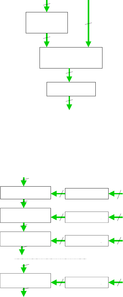
An Efficient Rijndael Encryption Implementation 181
128
128
128
128*(n+1)
Cipher Text
Transform
Rijndael-impl
Inverse-transform
Plain text block Round Keys
Fig. 1. This figure contains the high level view of the Rijndael encryption circuit. The
transform function consists of 16 parallel ciruits for T
∗
.x, where x ∈ GF (2
8
) and T
∗
is
the matrix to convert elements from GF (2
8
) to elements of composite field as decided
by section 5. Similarly, Inverse-transform consists of 16 parallel circuits for (T
∗
)
−1
.x.
Circuits for the multiplication of a constant matrix with a vector are obtained from
the method given in [11]
128
128
128
Add_Round_Key
Transform
128 128
Transform
128 128
128
Transform
Round_1
128
128 128
128
Transform
128 128
Round_2
Round_n
Key_2
Key_0
Key_1
Key_n
Fig. 2. This figure describes the rijndael-impl block in Figure 1
182 A. Rudra et al.
128
128
128
128
128
128
128
128
128
128
128
Key_i
Byte_sub
Shift_row
Mix_coloumn
Add_Round_Key
Add_Round_Key
Shift_row
Byte_sub
Key_n
Round_i (0<i<n) Round_n
Fig. 3. This figure shows the composition of each round. Note that in our implementa-
tion, n=10. Shift
row does not require any gate. Add Round Key is simply the EXOR
of the corresponding bits of the two inputs
i_1 i_8
o_8
Inverse8
Affine
Inverse8
Affine
i_113 i_128
o_128
Inverse8
Affine
i_9 i_16
o_16o_1 o_9 o_113
8
8
8
8
8
8
8
8
8
Fig. 4. This figure shows the implementation of the Byte sub operation. Affine has 16
parallel circuits for calculating T
∗
A(T
∗
)
−1
.x + H(c)
An Efficient Rijndael Encryption Implementation 183
32
32
32
32
Linear_comb Linear_comb
o_97 o_128o_32
i_1 i_32
o_1
i_97 i_128
Fig. 5. mix
column
H(02).x H(03).x
Add8
Add8
Add8
H(02).x H(03).x
Add8
Add8
Add8
H(02).x H(03).x
Add8
Add8
Add8
H(02).x H(03).x
Add8
Add8
Add8
i_1 i_8
o_1 o_8
i_9 i_17 i_24
o_9 o_16 o_24 o_32
i_16
i_25
i_32
o_17 o_25
All datapaths are 8-bit wide
Fig. 6. This figure describes the linear comb operation from Figure 5. Add8 is simply
the EXOR of the corresponding bits of the two inputs
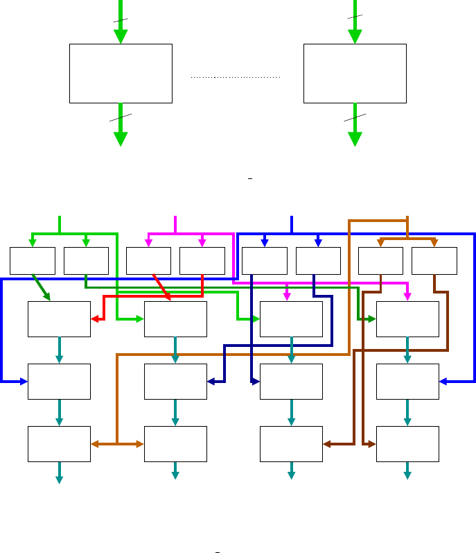
184 A. Rudra et al.
Add4 Cnst_mult11 Cnst_mult11
Cnst_mult1
Add4 Add4
Add4Add4
H(02).x
H(03).x
i_8
o_5 o_8
o_1 o_4
o_5 o_8
o_4o_1
i_5
i_1
i_4
All datapaths are 4-bit wide
Fig. 7. This figure shows the circuits for calculating H(02).x and H(03).x; Add4 is
simply the EXOR of the corresponding bits of the two inputs. Const
multi evaluates
the constant multiplication ω
i
.x, where ω is the primitive element of GF (2
4
) and
x ∈ GF (2
4
). These circuits have been obtained from [11]
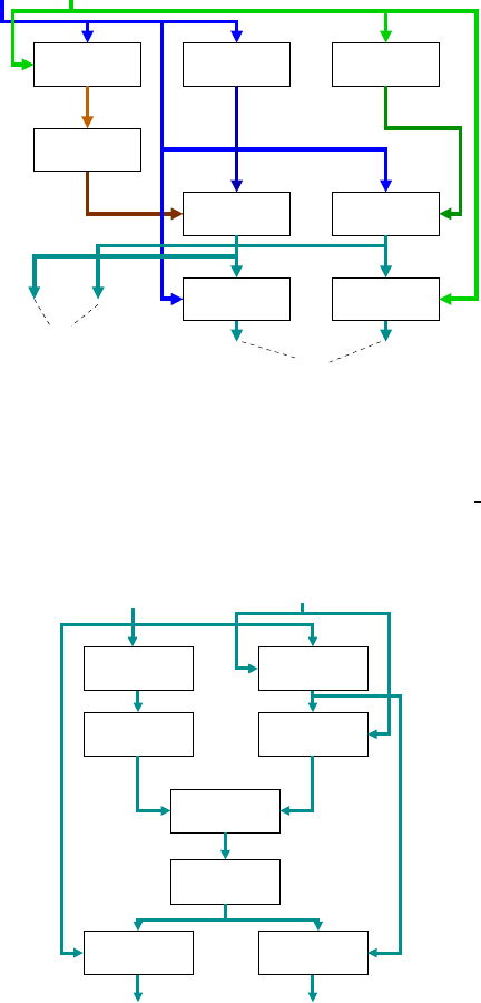
Inverse4
Square4 Add4
Mult4Cnst_mult14
Add4
Mult4 Mult4
i_5 i_8
o_1 o_4 o_8o_5
i_1 i_4
All datapaths are 4-bit wide
Fig. 8. This figure 8 shows the Inverse8 operation in Figure 4. Square4 is from [11];
Mult4 and Inverse4 are from [9]
